Electronic Corp. of America 132
| Model: | 132 |
| Manufacturer: | Electronic Corp. of America (ECA) |
Schematics Content
Page 1:
CIRCUIT. 7 Tube, Superheterodyne
FREQUENCY RANGE 540 to 1720 KC
INTERMEDIATE FREQ. 455 KC
POWER INPUT 110 to 125 V, AC - DC
POWER CONSUMPTION 60 Watts
ANTENNA Built-in Loop
SPEAKER Alnico V PM Dynamic 6"
V.C. IMPEDANCE 3.2 ohms at 400 Cycles
POWER OUTPUT 3 Watts Undistorted
Page 2:
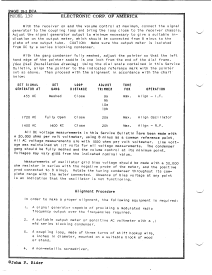
With the receiver on and the volume control at maximum, connect the signal generator to the coupling loop and bring the loop close to the receiver chassis. Adjust the signal generator output to minimum necessary to give a suitable indication on the output meter, which should be connected from B minus to the piate of one output tube. CAUTION: Make sure the output meter is isolated from DC by a series blocking condenser.
With the gang condenser fully meshed, adjust the pointer so that the left hand edge of the pointer saddle is one inch from the end of the dia frame. (See Dial Installation drawing) Using the dial scale contained in this Service Bulletin, align the pointer to the indicated reference mark with the pointer set as above. Then proceed with the alignment in accordance with the chart below:
All DC voltage measurements in this Service Bulletin have been made with a 20,000 ohms per volt voltmeter, using B minus as a common reference point. AI AC voltage measurements are with 1000 ohms per volt voltmeter, Line volt age was maintained at 117 volts for all voltage measurements. The condenser gang should be fully meshed and the volume control at its minimum point, Voltages may vary +/-10 % from the indicated nominal value.
Measurements of oscillator grid bias voltage should be made with a 50,000 ohm resistor in series with the negative probe of the meter, and the positive prod connected to B minus. Rotate the tuning condenser throughout its complete range with the meter connected. Absence of bias voltage at any point is an indication that the oscillator is not functioning.
Alignment Procedure
In order to make a proper alignment, the following equipment is required:
1. A signal generator capable of providing a modulated radio frequency output over the frequencies required.
2. A suitable output meter or sensitive AC voltmeter with a l mfd series blocking condenser.
3. A coupling loop, made of three turns of stiff hookup wire, 4 inches in diameter, mounted on a suitable block of wood or stand.
4. A non-metallic screwdriver,
Page 3:
Replacement of I.F. Transformers
When replacing intermediate frequency transformers, either input or output, use caution to observe original lead dress.
Page 4:
Replacement of Dial Drive Cord
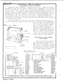
Completely remove remainder of defective dial cord. lospect all pulleys and make sure they revolve freely. Determine that no grease or oil is present on any pulley surface. Attach the cord spring, part # A - AQ589, to one end of the drive cord. Fully mesh the gang condenser and hook the spring to the hole closest to the cord cutout on the dial drum. Proceed to string dial cord in accordance with the detail drawing. Take two full turns around the drive drum, part # A- Q772. Pull the cord snug at this point. Wrap one complete turn around gang drum and pull cord snug. Securely tie free end of cord to the cord spring. Next, adjust spring tension by moving the hook end of the spring into the next spring hole.
Clip the pointer on to the dial cord with sufficient tension so as to prevent slippage and adjust pointer position, so that with fully meshed gang, the left edge of the pointer saddle is one inch from the edge of the dial support frame. Insert chassis in cabinet and check pointer and scale agreement. Then make final adjustment of pointer position. Remove the chassis and firmly crimp the pointer prongs on the dial cord, and secure with a small drop of speaker cement.
Replacement of Audio Output Transformers
When replacing the audio output transformer, original lead dress must be maintained. If either primary or secondary windings are reversed, the set will have a a severe audio oscillation, due to the inverse feedback network.


